Lithium-ion battery pack design: from equipment requirements to production release.
A professional framework for defining cell architecture, current path, BMS, thermal behavior, enclosure, interfaces and validation—without unsafe DIY assembly instructions.
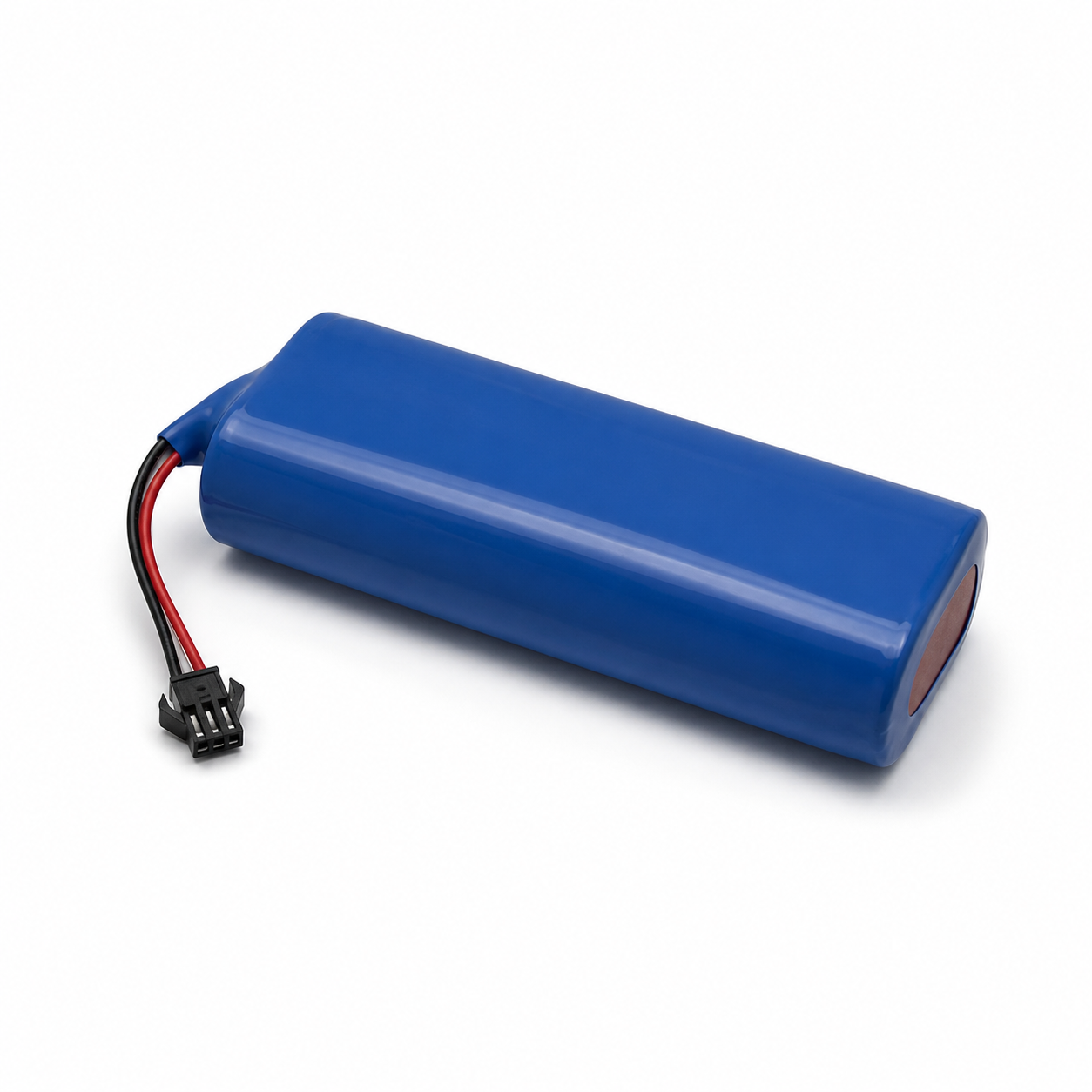
Start with the duty profile, then make the electrical and mechanical design agree.
A lithium-ion battery pack design is not complete when voltage and capacity are selected. The design must trace the equipment load, runtime, charge source, space, environment, service strategy and regulatory scope into a cell platform, S/P architecture, current path, protection concept, thermal design, enclosure and verification plan.
For OEM procurement, the useful output is a controlled specification: drawings, electrical limits, interface definition, software or communication expectations, acceptance criteria and a documented route from prototype to repeat production.
Convert equipment behavior into measurable battery limits.
The requirements document is the common reference for cell selection, BMS logic, mechanical integration, validation and purchasing.
| Load profile | Record steady-state current, transient peaks, duration, frequency, regenerative or capacitive events and low-voltage behavior. |
|---|---|
| Energy and runtime | Use the real duty cycle, conversion losses, reserve and end-of-life target—not Ah alone. |
| Charging | Define charger source, voltage/current limits, charge time, temperature restrictions and host interlocks. |
| Environment | Temperature, altitude, vibration, shock, water/dust exposure, storage and service conditions. |
| Lifecycle and supply | Cycle/calendar targets, service life, annual quantity, cell continuity, change control and end-market requirements. |
Select chemistry, cell format and series/parallel arrangement as one decision.
LiFePO4 is often chosen for cycle life and thermal-stability priorities; other lithium-ion systems may suit energy-density or space constraints. The application decides.
Chemistry & cell
Review voltage window, energy/power capability, temperature, life, supplier traceability and availability.
Series count
Set nominal and full-charge voltage against the host, charger and insulation/protection architecture.
Parallel count
Meet energy and current needs while controlling sharing, fusing and cell consistency.
Current path
Size interconnects, busbars, cables, connectors, fusing and switching around load, resistance and heat.
Define what the BMS monitors, decides and actuates.
Threshold values and redundancy are project-specific; a generic BMS label cannot prove suitability.
| Monitoring | Cell/group voltage, pack voltage, current and relevant temperatures with defined accuracy and coverage. |
|---|---|
| Protection | Over/under-voltage, over-current, short-circuit and temperature responses coordinated with charger and host. |
| Balancing & estimation | Balancing strategy plus SOC/SOH methods tied to the chemistry, current sensing and usage profile. |
| Execution | MOSFET or contactor architecture, precharge, service disconnect, isolation monitoring and fault-safe states where required. |
| Communication | CAN, RS485, UART, SMBus, diagnostics, event logs, firmware/configuration and change control. |
Design around heat, interconnects, swelling, vibration and service access.
Pack temperature can be non-uniform, and interconnect losses add heat. Simulation can guide design but does not replace representative hardware tests.
Heat sources
Estimate cell and interconnect losses under charge, continuous load and transient events.
Temperature control
Set sensor locations, gradients, cooling/heating method, control logic and failure response.
Mechanical restraint
Define cell support, compression where applicable, clearances, insulation, vibration control and vent paths.
Enclosure & interface
Coordinate mounting, sealing, pressure/vent strategy, terminals, cable routing and maintenance access.
Prove the design before the production configuration is frozen.
The verification matrix should state test conditions, samples, acceptance criteria and responsibility.
| Engineering samples | Check electrical behavior, fit, charger/host interface and communication on the intended equipment. |
|---|---|
| Design verification | Exercise load, charging, temperature, protection, thermal, mechanical and environmental cases appropriate to the project. |
| Compliance evidence | Confirm UN 38.3 and other transport/market evidence for the exact battery type and destination. |
| Production release | Freeze BOM/configuration, drawings, software, work instructions, inspection and end-of-line acceptance. |
| Change control | Assess cell, BMS, firmware, enclosure and process changes for revalidation and document impact. |
Practical procurement questions.
How do I design a lithium-ion battery pack?
Begin with equipment requirements, then select and validate the chemistry/cell, S/P architecture, current path, BMS, thermal and mechanical design, interfaces and production controls. Do not start from a wiring diagram.
Can capacity be calculated from runtime alone?
Only provisionally. Load profile, voltage window, conversion losses, temperature, discharge rate, reserve and end-of-life target affect usable energy.
Does a BMS make a pack safe by itself?
No. Safety depends on cells, current path, protection architecture, charger/host behavior, thermal and mechanical design, validation, manufacturing and correct use.
Official references used for this guide.
Always confirm the current rule, exact model and destination before relying on a document.
- NREL: Li-Ion Battery Thermal Characterization for Thermal Management Design — thermal behavior must be evaluated at cell, interconnect and pack level; the research is not a product test report.
- Texas Instruments: battery monitor, protector or gauge — explains functional boundaries among monitoring, protection and gauging.
- Texas Instruments: BMS monitoring, protection and balancing — describes common BMS functions; project thresholds and architecture still require validation.
- PHMSA Lithium Battery Guide 2024 — official U.S. guidance on classification, UN 38.3 test summaries and shipper responsibilities.
Turn your equipment requirement into a battery specification.
Send the load, runtime, space, interface, environment, quantity and target market for an engineering review.